ASSEMBLY INSTRUCTTIONS
Step 1
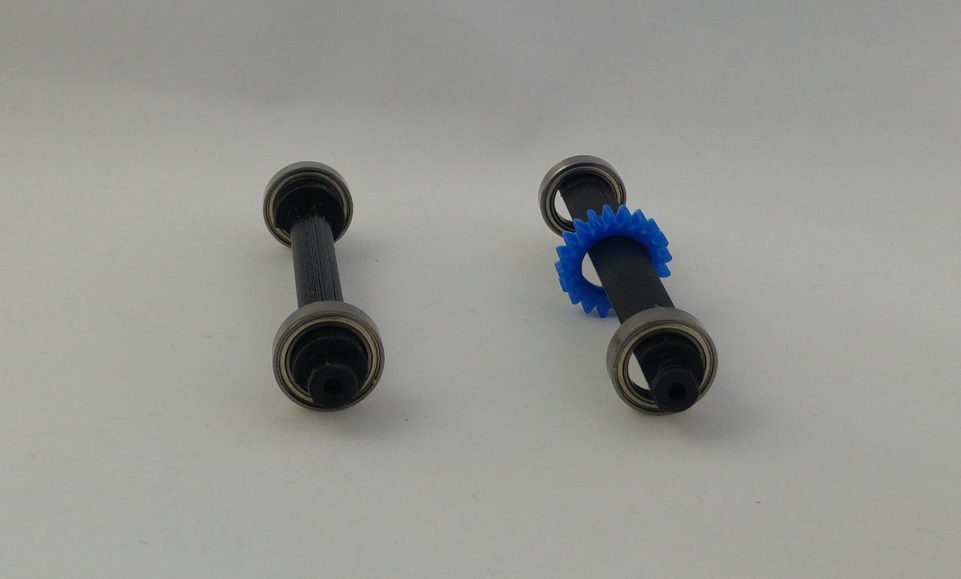
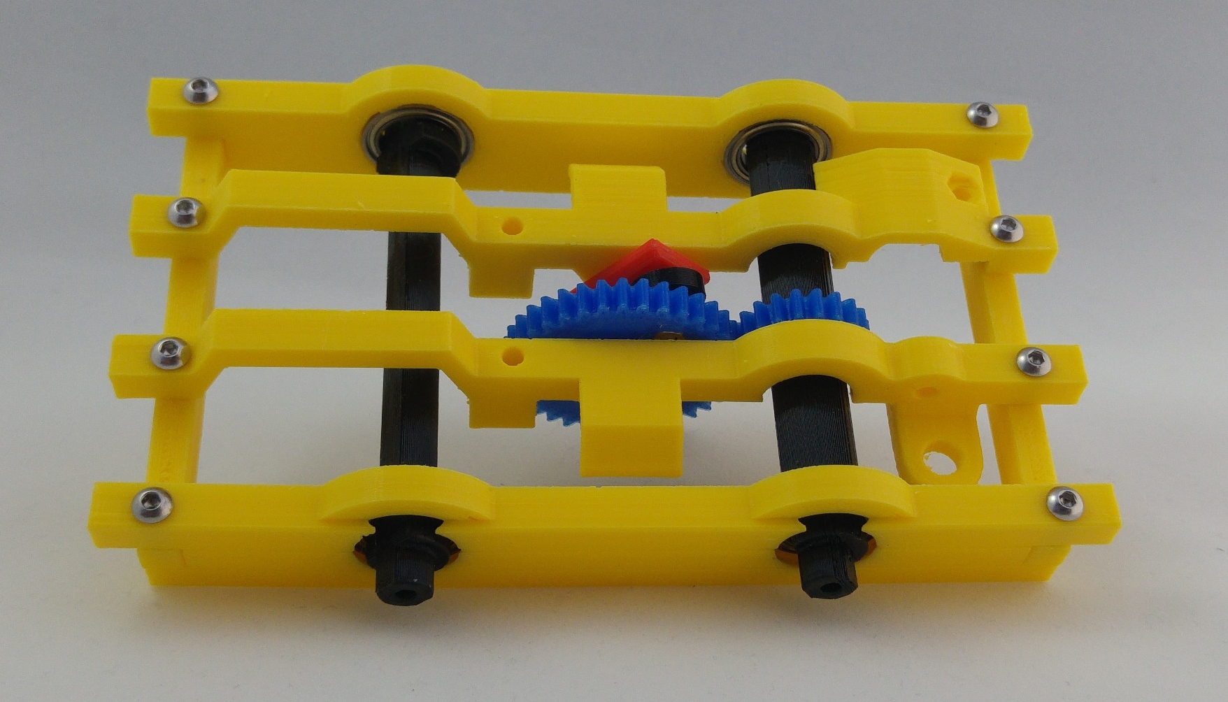
First, insert axle gear into rear axle. Then insert four bearings (18x12x4mm) into the front and rear axle.
Step 2
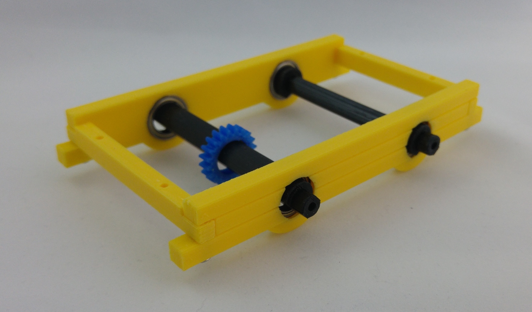
Insert axles (with bearings) into the body sides and hold them to body front parts with four M3x10mm screws. See the picture for correct orientation.
Step 3
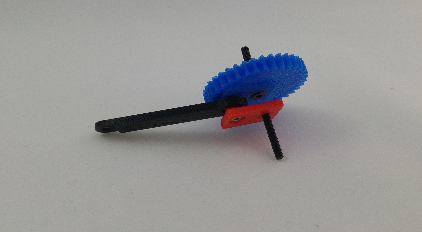
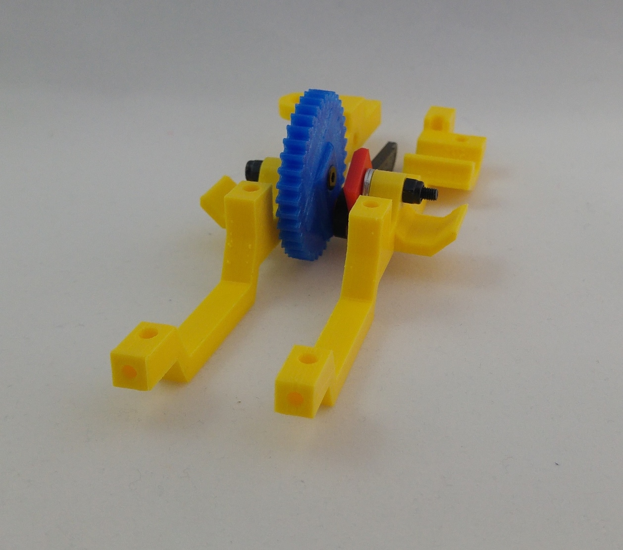
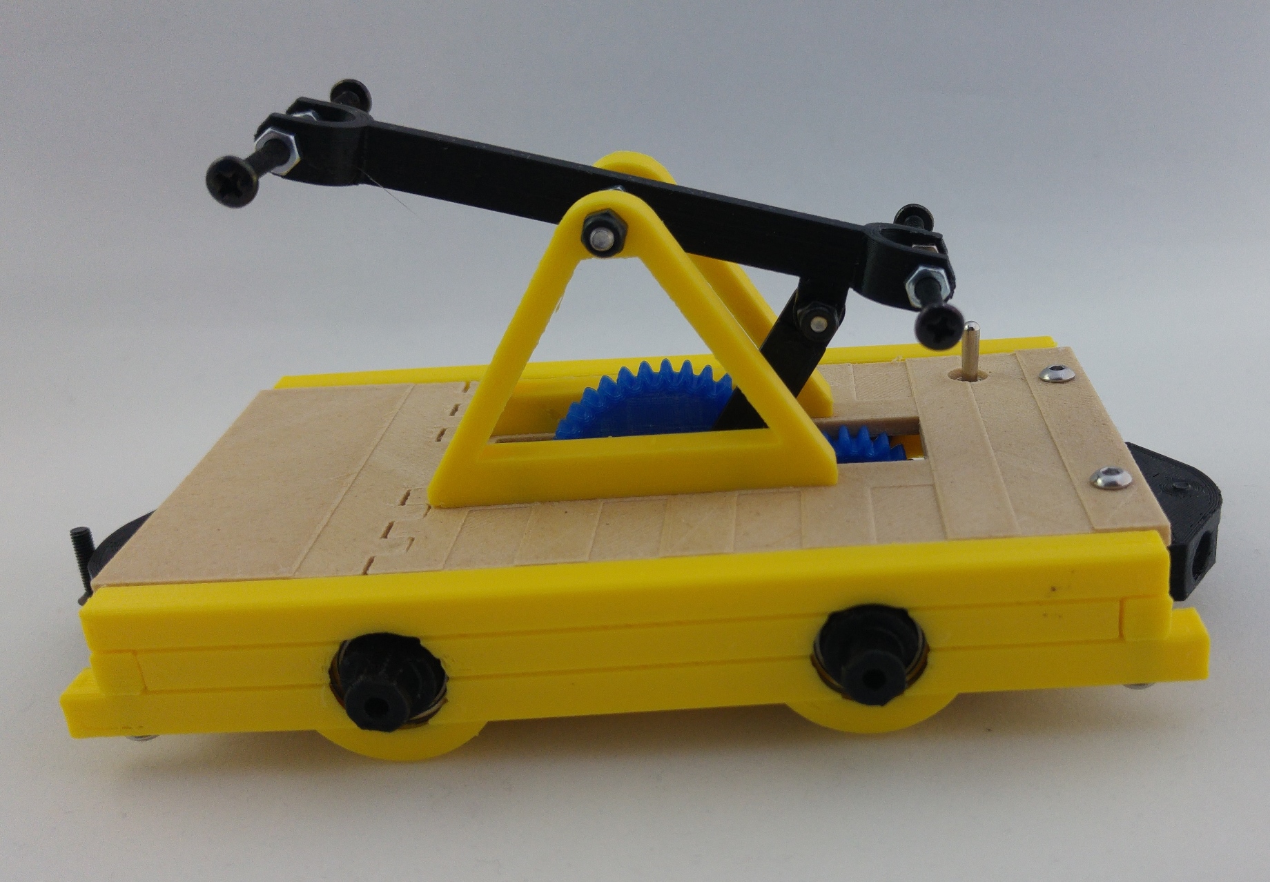
This can be a tricky part. Insert first two M3x20mm countersunk screws into the main gear and main-gear-2 part respectively. Now, insert the connecting rod and use one M3x12mm screw and nut to secure it, but don't overtighten it too much for now (this is because you will need to move them a bit to tighten the screws in the following steps). See picture for more details.
Step 4
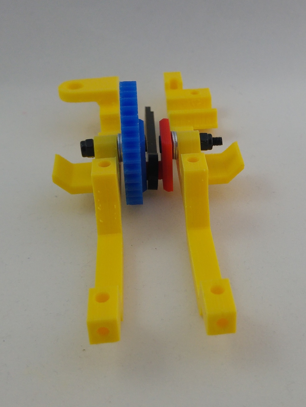
First, insert two M3 washers in each M3x20mm screw and using body-arm and body-arm-motor, assemble the main gear from previous step. Use two lock nuts but don't overtighten them as the screws have to rotate freely. See picture.
Step 5
When previous step has finished you can now tighten the M3x12mm screw and nut from main gear.
Step 6
Now, put body arms in place and secure them with four M3x10mm screws.
Step 7
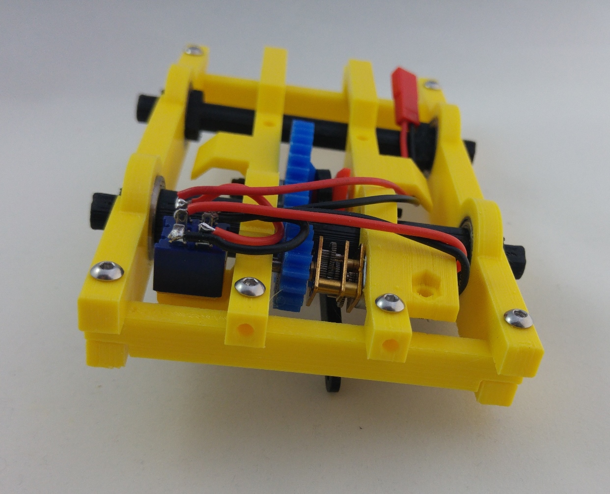
Follow the picture for soldering the switch, motor and battery cable. Don't be afraid about this step, it is not a complicated soldering job. I'm not very experienced myself 😛 I soldered it in a position that fits the car perfectly, so I suggest you use the same layout.

Step 8
Put switch and motor in place.
Step 9
Secure motor with the motor bracket and one M3x10mm screw and nut. Now secure the switch with the switch nut. I suggest you try the motor by connecting the battery to ensure everything works correctly.
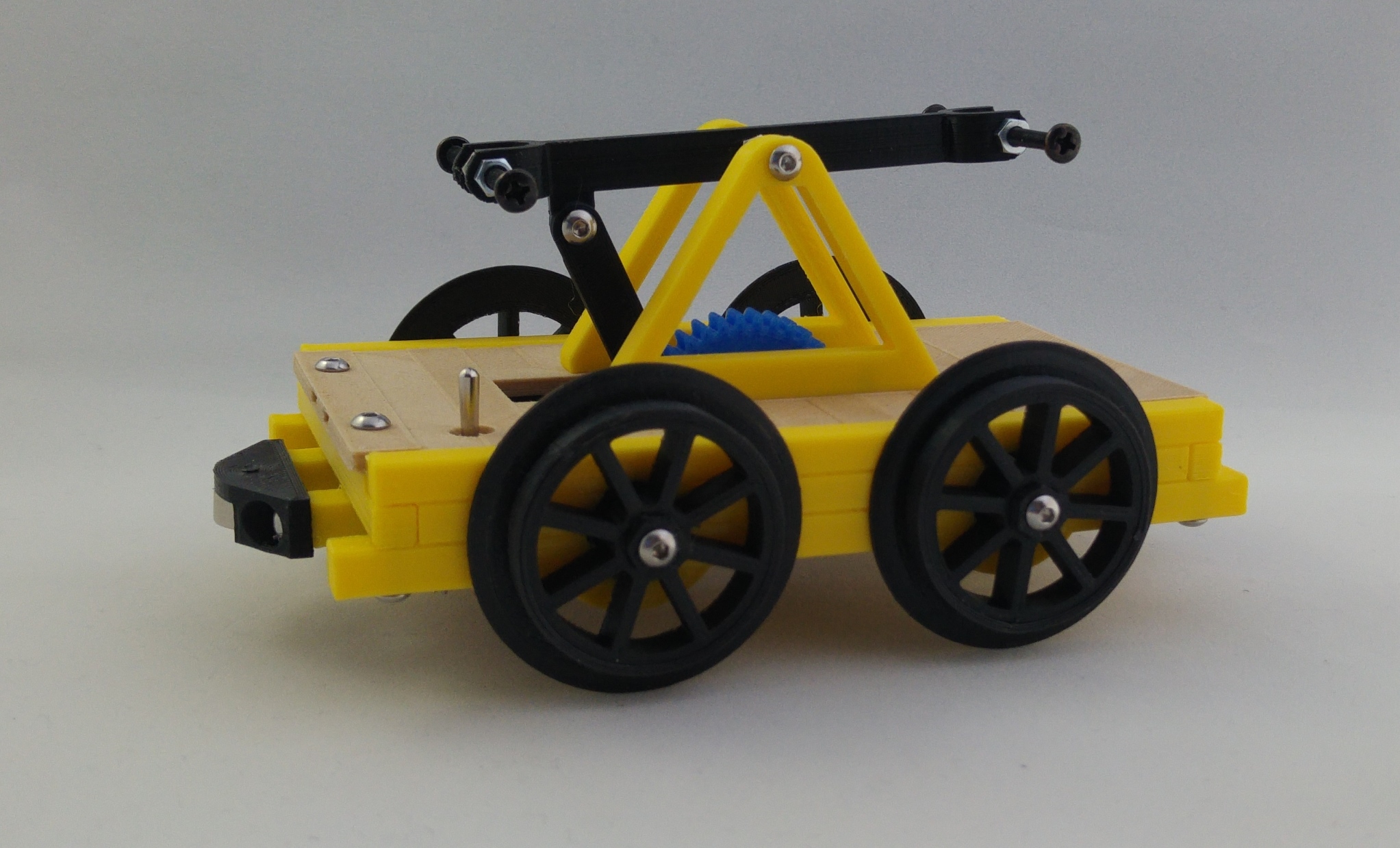
Step 10
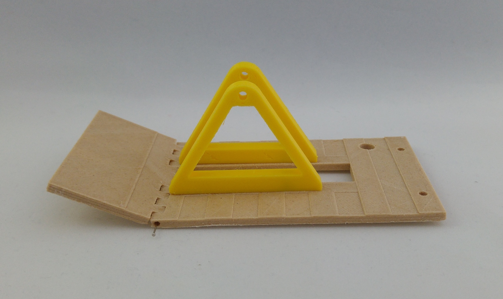
Using four M3x25-30mm screws and 8 nuts, assemble the swing.

Step 11
Put the platform and the bridge parts toghether with two M3x8mm screws. See the picture to mount the correct ones in this step.

Step 12
Now insert the needles into platform and assemble the trunk.
Step 13
Mount the platform into the chassis with two M3x8mm screws above (paltform to the chassis) and two M3x25 screws below (through chassis to bridge).
Step 14
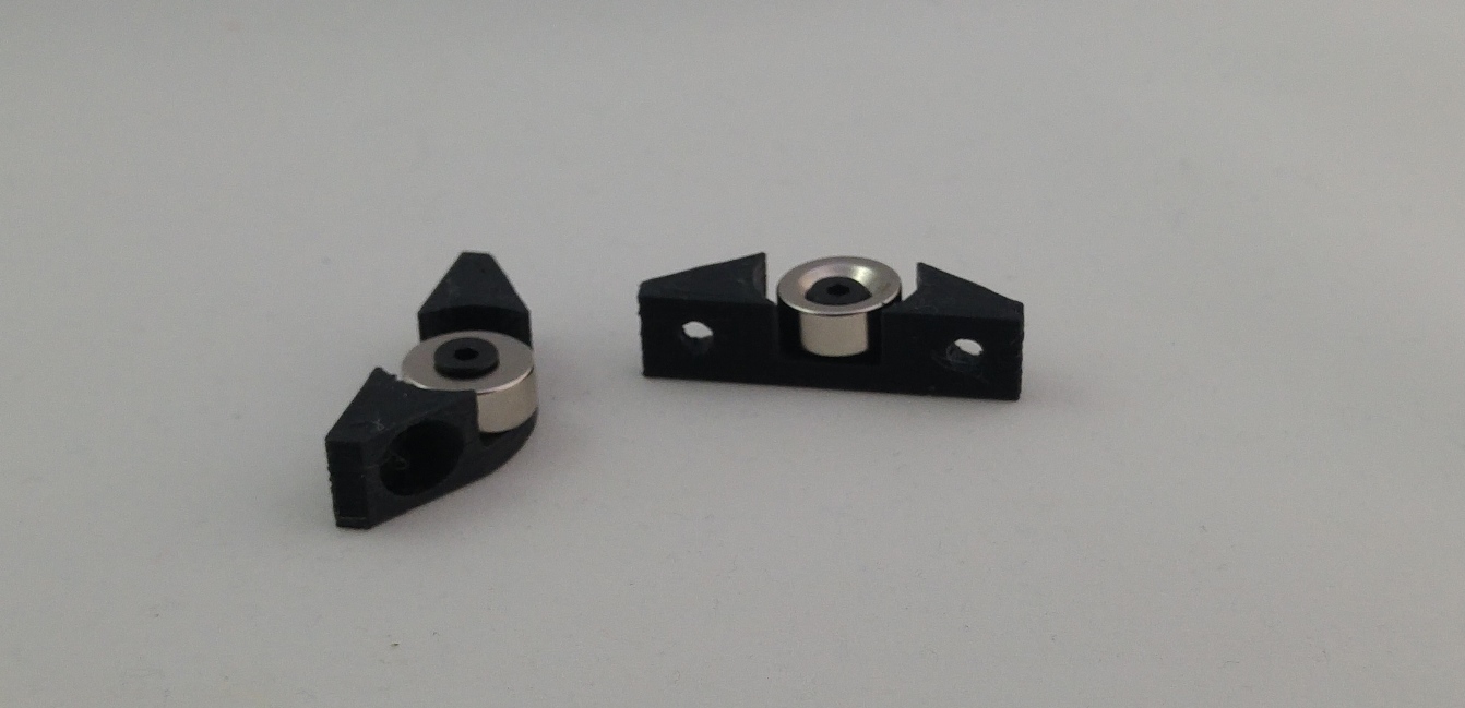
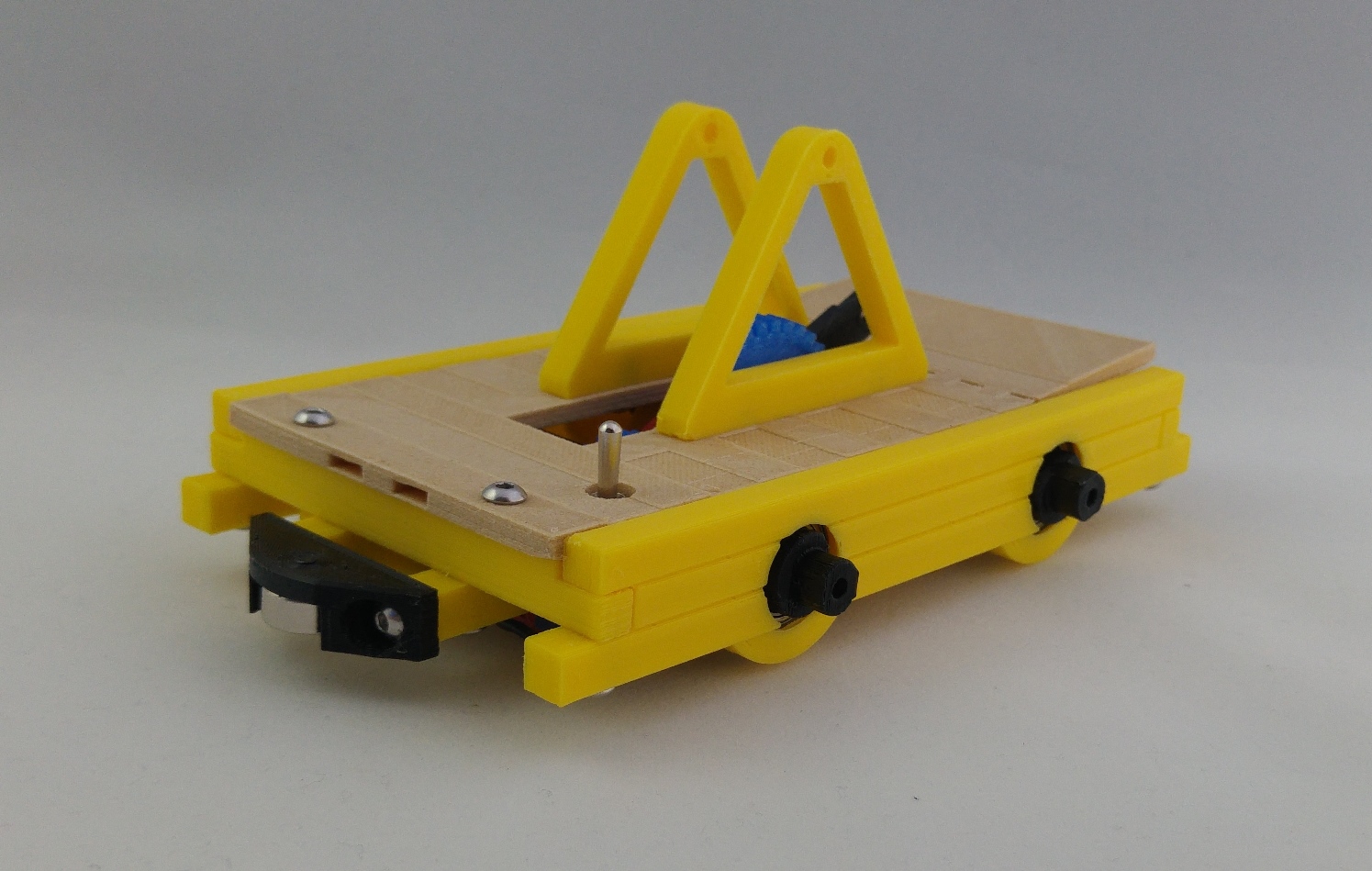
Secure the two magnets into the bumpers with two M3x10mm screws. Bear in mind the polarity of the magnets. You'll have to mount one opposite to the other in order for them to atract each other.
Step 15
Then secure the bumpers to the car with four M3x8mm button screws.
Step 16
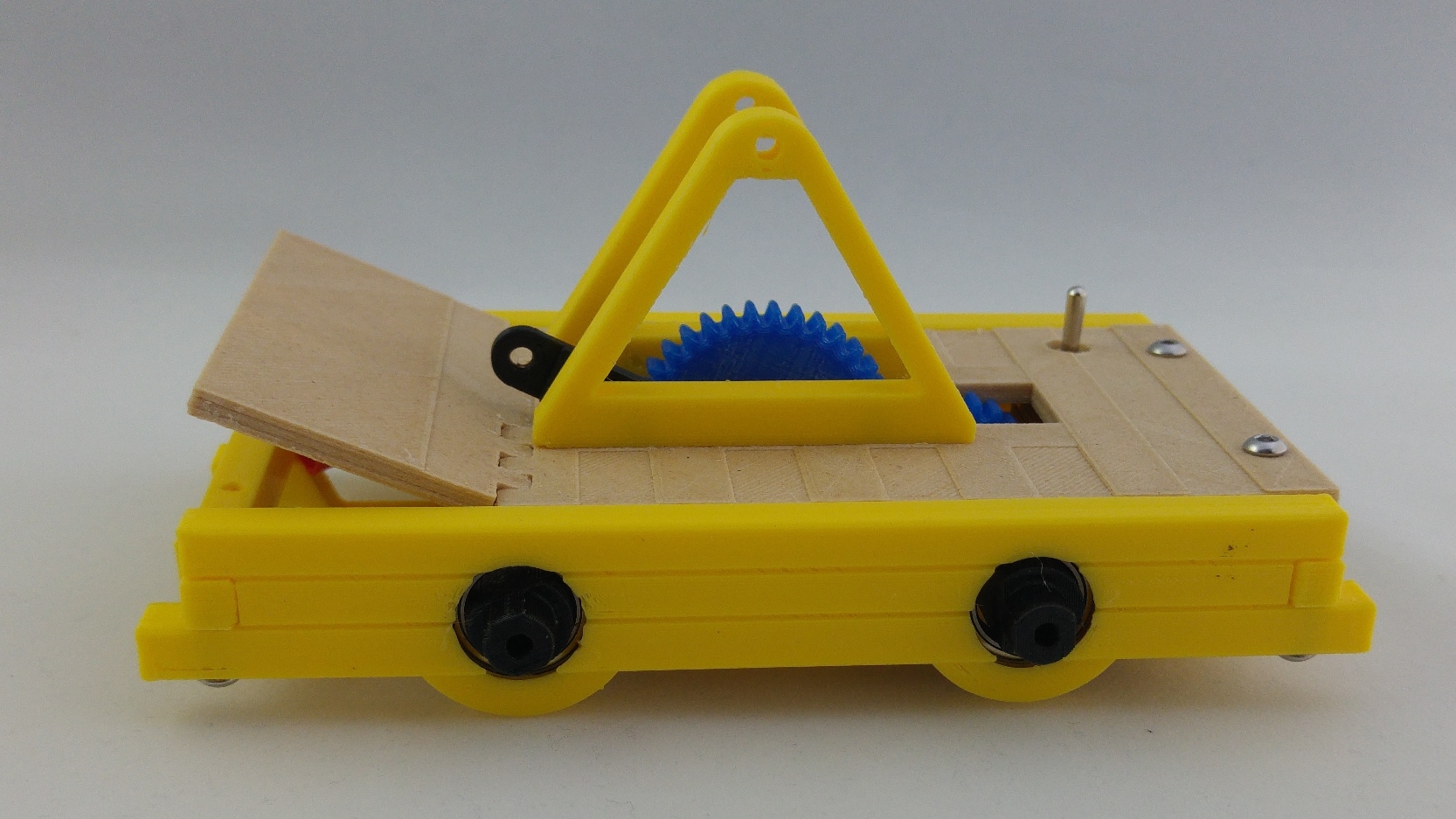
With one M3x35mm screw, two nuts and a lock nut mount the swing on the bridge.
Step 17
Secure the connecting rod to the swing with one M3x10mm screw and a lock nut.
Step 18
Insert the tyres into the rims. Now use four M3x8mm screws and the wheel plastic nuts to mount four wheels.
Step 19 (optional)
Print two drivers and use eight 15x6.5x2mm magnets to secure them in place using the holes in the side of the platform and trunk.

And that's it, your Railroad Hand Car is finished!! Now just print your tracks, mount them, connect the battery and enjoy!!
Hello,
I made one,and I like it !
Thank you !
That’s great news! Glad you like it!
I would really appreciate if you upload some pictures to https://www.myminifactory.com/object/43249 (you have to search for community prints and upload yours) so we can see how it turned out!!
Thanks for sharing!
A very nice project ,I have started with the drivers ,but it seems impossible to print them with moving parts , the only part that moves is the arms at shoulder height.Do you have some suggestions ? Can I print the parts separately and then joint them ?
Hey, glad you like it! 🙂
I printed it without problems but it’s true that the gap between the moving parts it’s a bit tight and the result will depend on the printer. Unfortunately, the design doesn’t allow to print separately and join later as it is.
But here you have some ideas you could try.
I have just uploaded a driver with slightly increased tolerances (search for more gap version). I haven’t had the time to try it yet, but it should work better on more printers. Just be gentle when getting it off the buildplate or it may break. You can also try lower layer height (to 0.1mm for instance).
Another thing you could try is to reduce the extrusion multiplier a bit. This depends on the printer and I don’t know the exact value for yours, but for example, I use 0.88 with my prusa hephestos and 0.94 with my ZYYX+.
Hope that helps!
Mate… All i can say is WOW 🙂 . This is going to be my next project. Love it.
Also is there any way you can upload a PDF of instruction please? Thanks heaps
Hey Brian!
Sorry, I don’t have it in PDF but you can print the page as PDF if you want to have it offline. Here is the pdf I printed from my post: https://drive.google.com/file/d/0B_Bh5ISU2CT5MVM3YTA2dWgyaFE/view?usp=sharing
Hope that helps!
Cheers for that. Appreciated. Just one other thing. What screw sizes did you use on the countersunk and the button head screws? Thanks. (Just they are not in the link above)
Done! I added the sizes to the part list 😉
So, I understand how this works, sort of. The driving axle, how is that gear secured to the axle? it looks free-floating in steps 1 and 2…..
Hey Nicholas,
Sorry for the delay.
Yeah, I see now that it seems to be floating in the picture but it is not. It’s just that the axle has a flat side in order to print correctly without supports.
The gear and axle have a dent to keep them in place. However, I suggest you use a drop of hot glue to avoid future possible movements.
Ah ok. Yeah I just made my own and I see what you’re talking about. I used some super glue on it so it’s never coming off haha.
That’s great news!
Please, if you can, upload a picture to the download page when it’s finished. I’d love to see it 🙂
Thanks!