Description
I have been wanting to use some stepper motors to design a clock for a long time, and finally I could find some time and IT IS HERE!
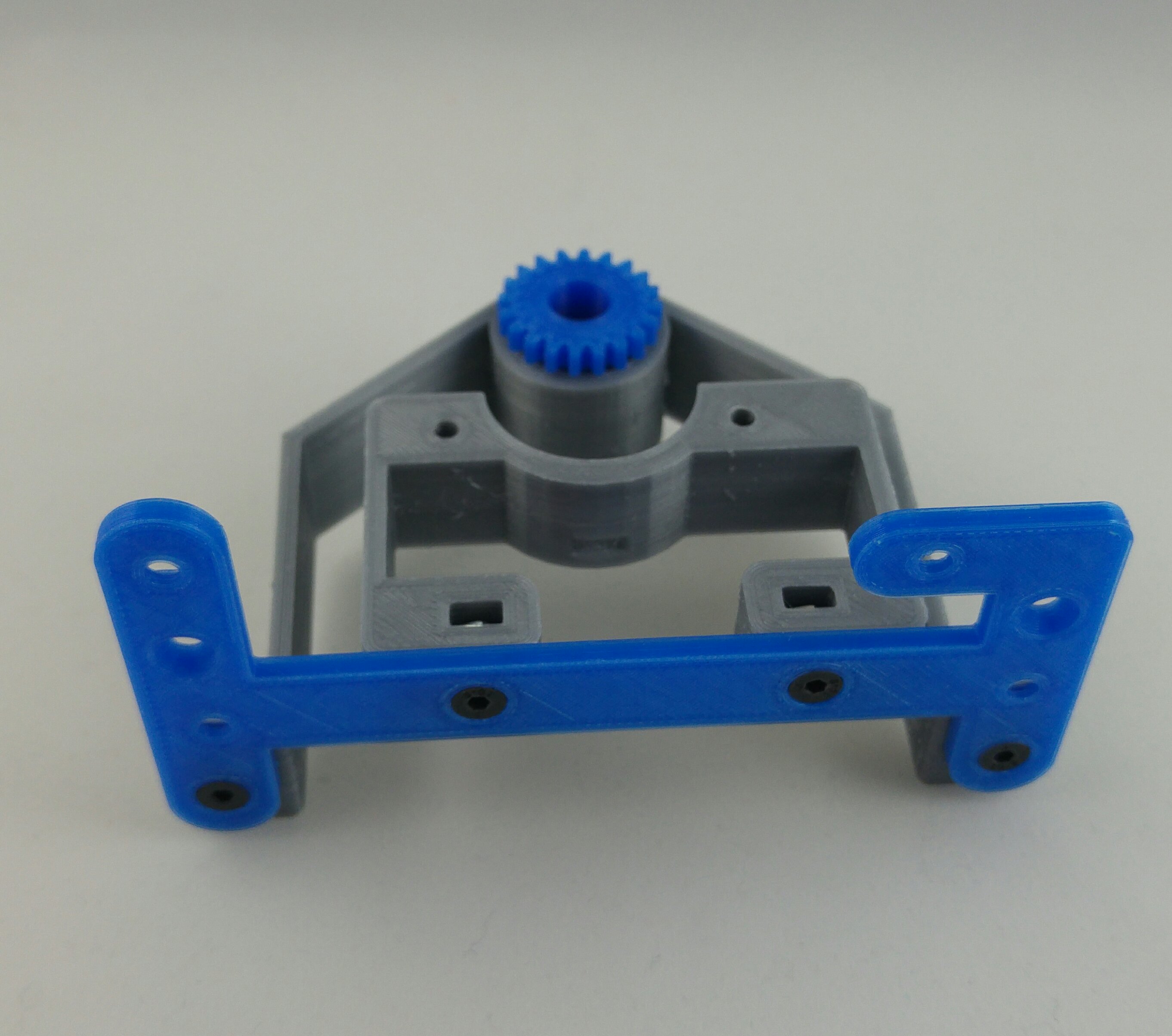
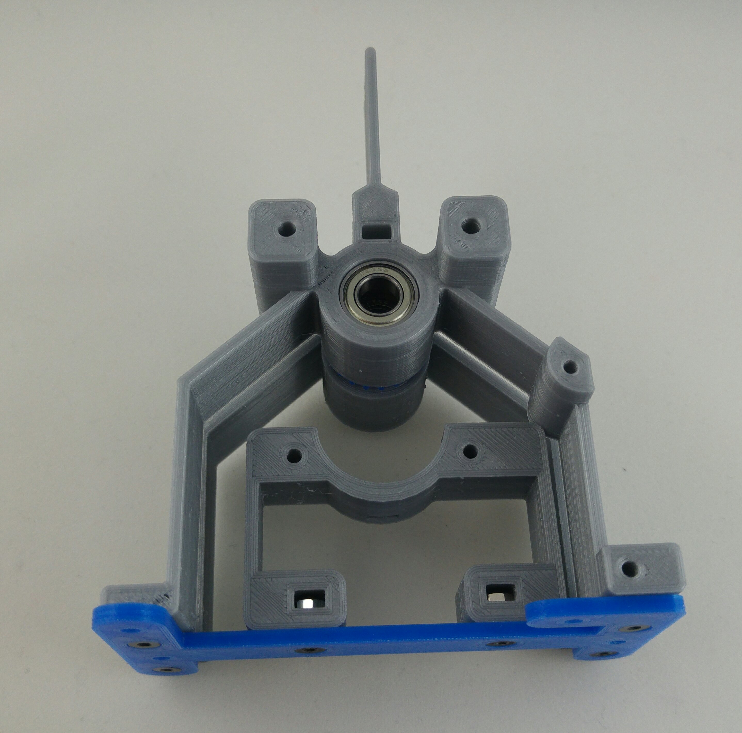
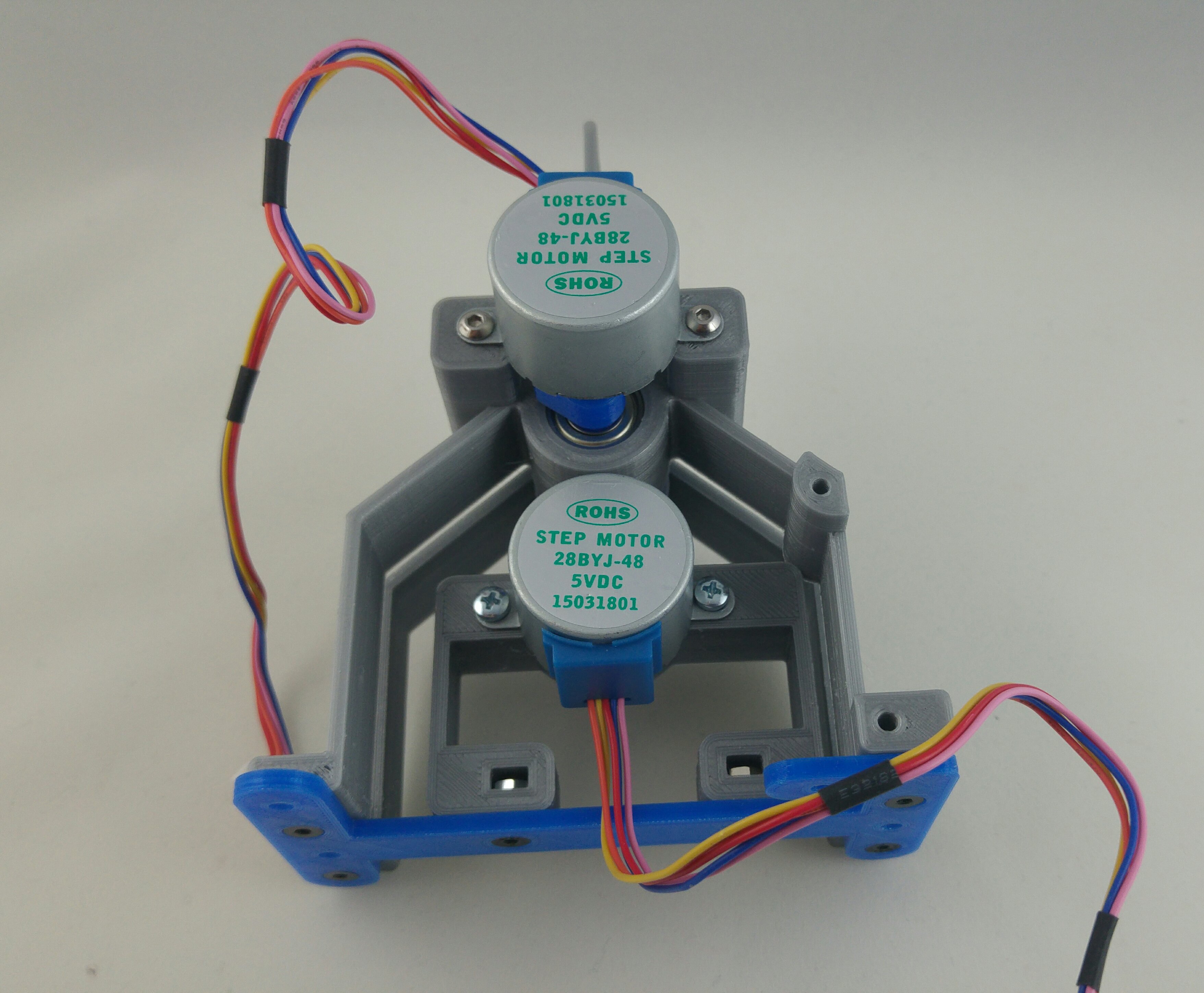
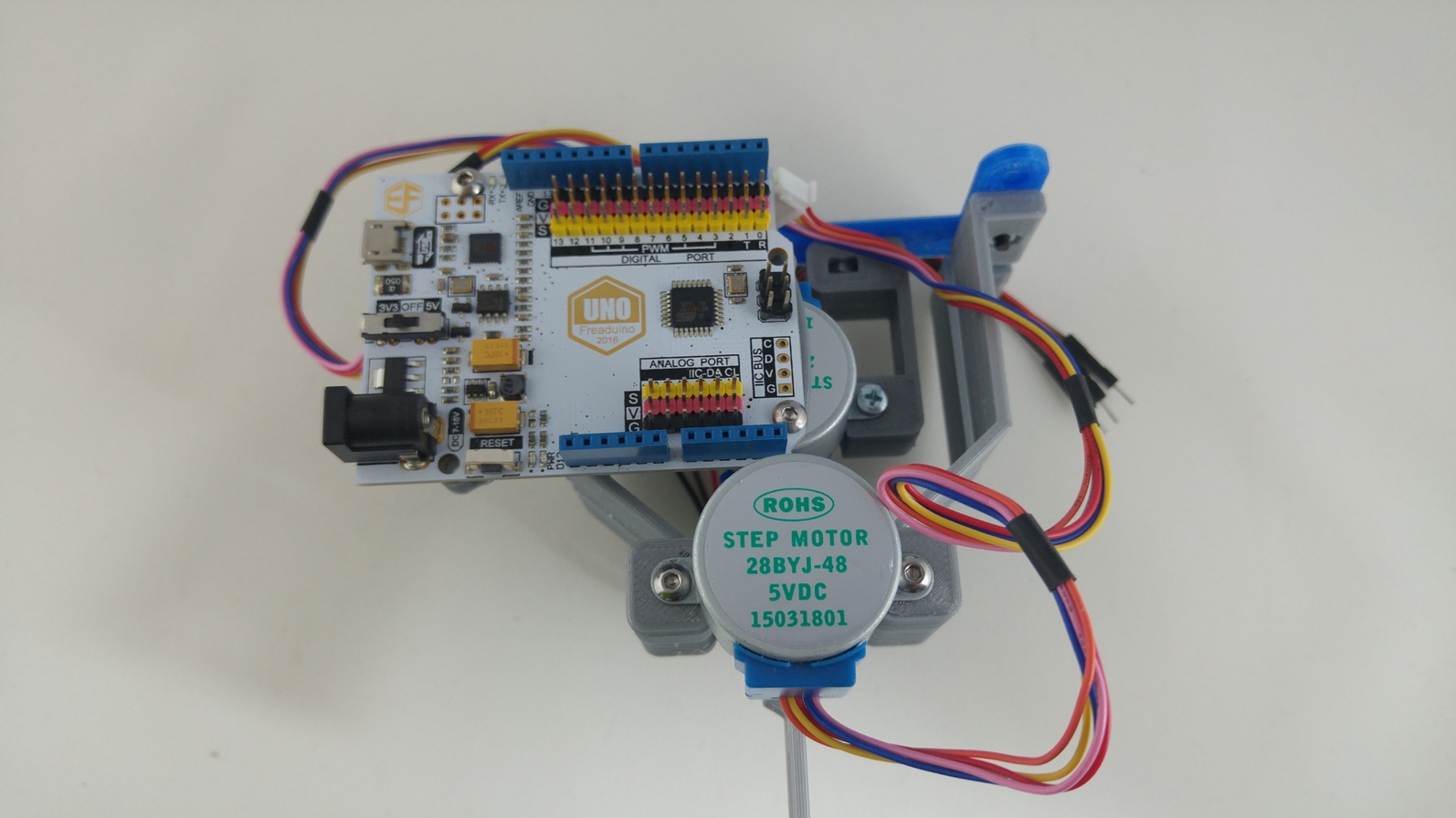
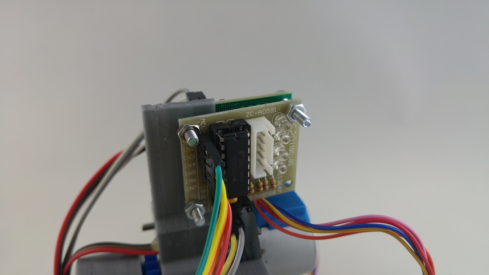
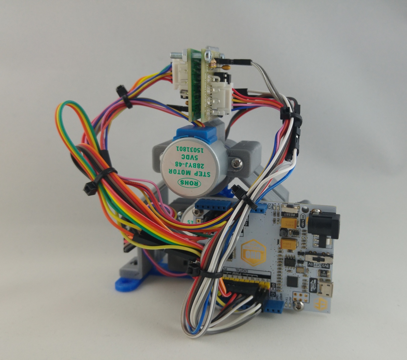
It uses two steppers to move hour and minute hands independently with 3D printed concentric shafts, while one Arduino compatible board controls everything.
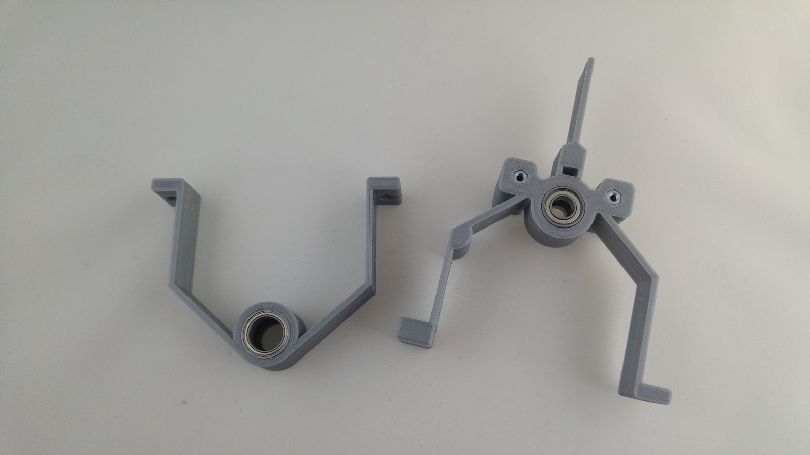
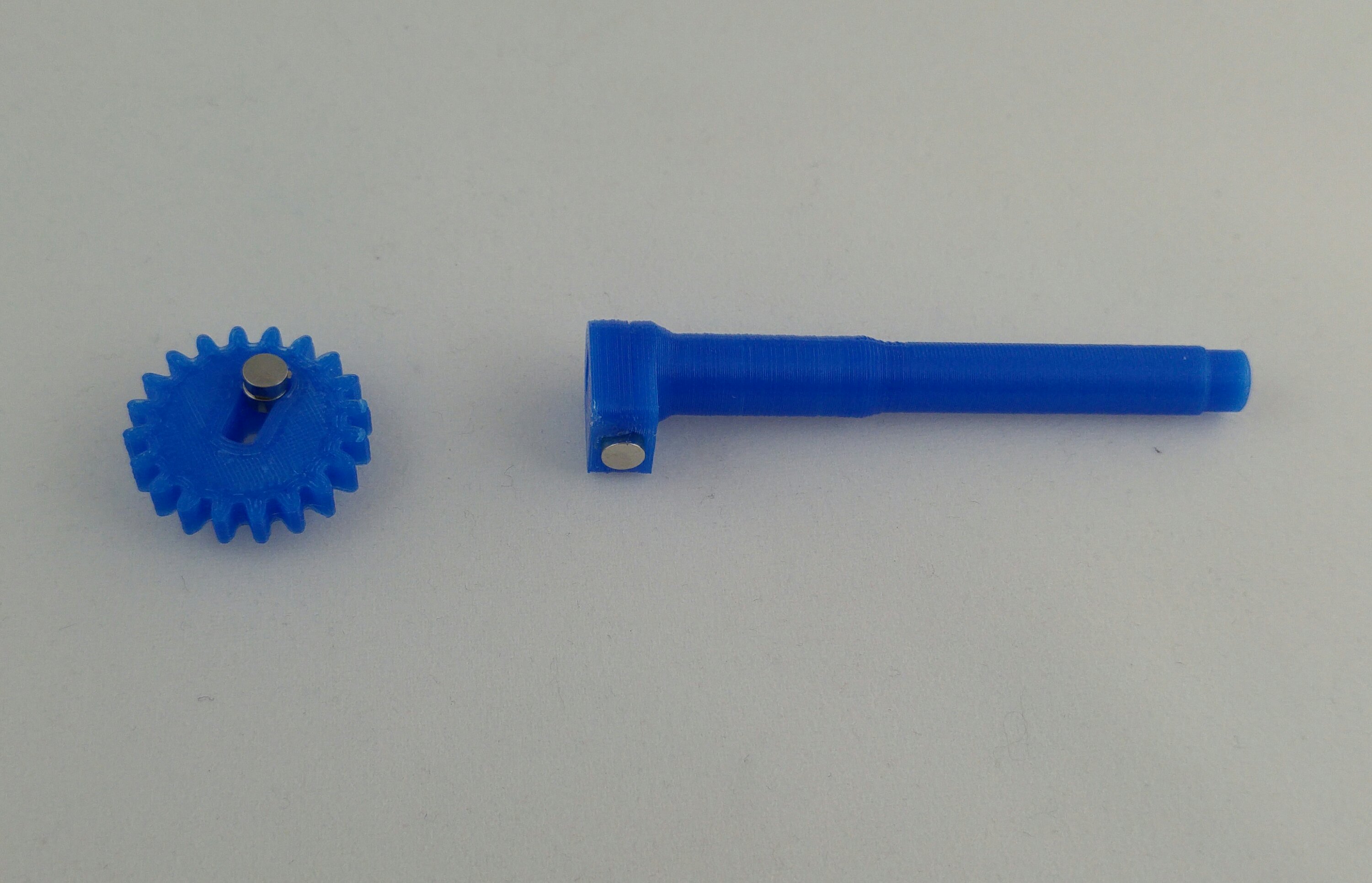
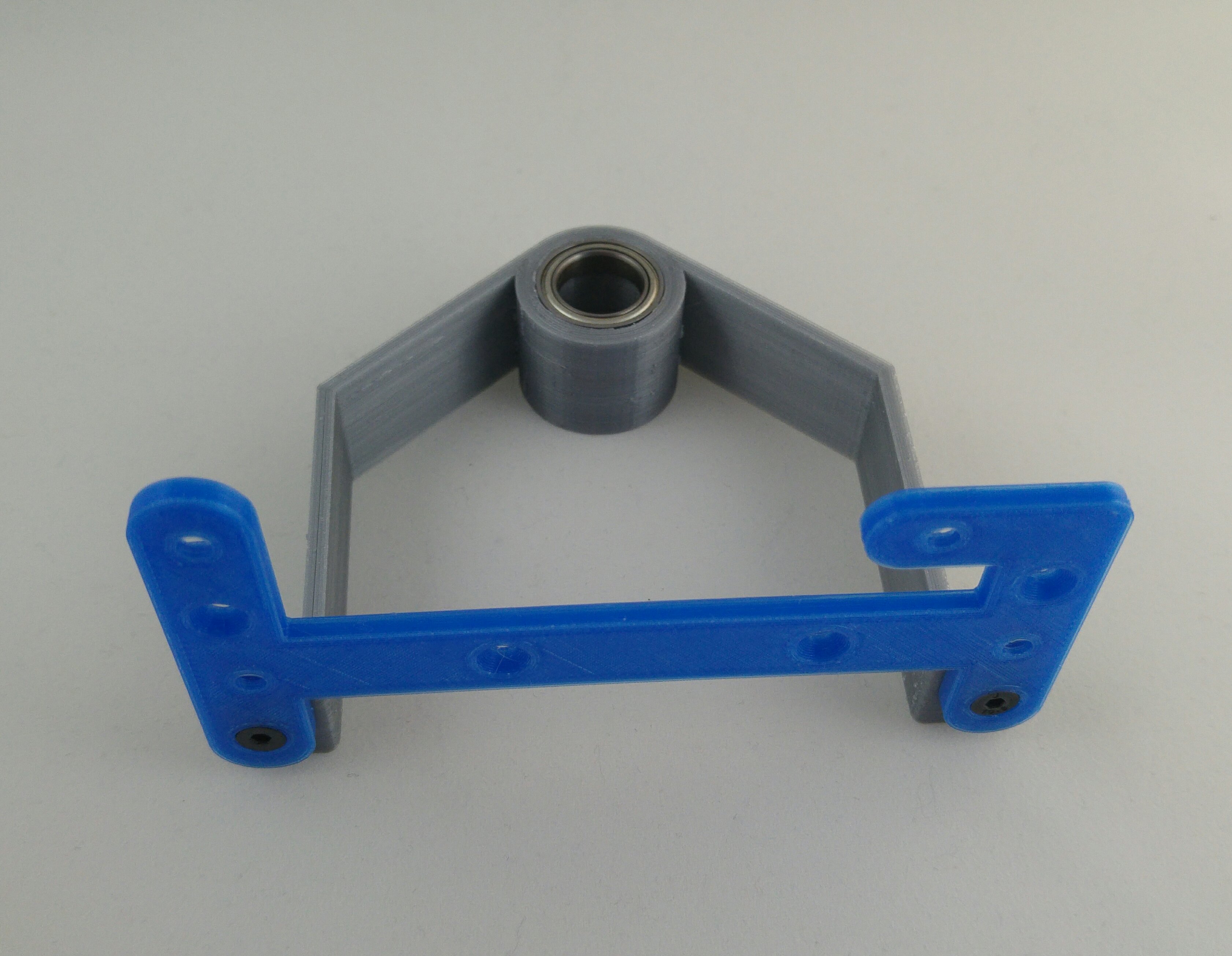
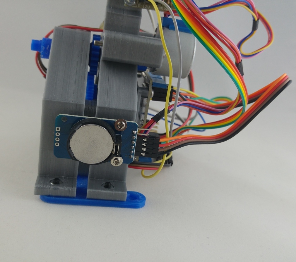
For me, there were two big challenges; designing the concentric shafts and the position detection system. I spent quite some time thinking about the design before the first approach. Then, when I printed the first version, I decided to change some major things to make it easier to assemble. Finally, after a couple of prints and tests, I’m quite satisfied with this final version. It uses two hall sensors to know where the initial position is and a concentric shaft system with bearings. It also uses a real time clock module to keep track of the time when it loses power, so you only have to set it the first time or when changing batteries.
You’ll find different “faces” (covers), so you can choose the one you like the most or have different models ready for swapping them depending on the occasion.
In addition, they are stackable, so you can print a couple of them and create some unique layouts and keep track of different time zones!!
Printing settings
All parts print without supports. The body is a long print (about 6-7hours). I decided to design it with 1.6mm wall so it prints with 4 perimeters (on 0.4mm nozzles).
I used PLA and printed all parts (except body) with 0.2mm layer height (body 0.3mm) and “standard” settings (3-4 perimeters and around 20% infill).
For the cover, there are two versions, the “normal” cover is supposed to be printed at 100% infill. On the other hand, the cover_infill part, is designed to be printed with different infill patterns and no top layers. Tinkering with the slicer settings, you can get some awesome original designs! With Simplify this is really easy to do, but if you’re using some other slicer you’ll need to change your printing settings accordingly.
Parts and components
In addition to the printed parts, you’ll need:
Code
The Arduino program comes with the stl files and last version can be downloaded from my github repository.
NOTE: Bear in mind that at the time of the release, the code is in beta version. It works but it may have some bugs/errors. Visit my github for latest updates.
You’ll need three libraries: RTClib, Accelstepper and wire.h that is already included with Arduino IDE.
First time use
The first time you use it, uncomment one of these two lines:
- //rtc.adjust(DateTime(2014, 1, 21, 3, 0, 0));//this sets time manually
- //rtc.adjust(DateTime(F(__DATE__), F(__TIME__)));//this sets time based on the compilation time of the computer
Once time is set, comment again and reupload the sketch. After the time is set for the first time, the RTC module will keep it synced as long as it has battery. If you change the battery, you'll need to uncomment this again. Batteries on the RTC clock module should last long enough.
Calibration
You’ll also need to calibrate the zero position. The code works like this: first minute motor moves until it detects the magnet and then hour motor does the same. At this moment, calibration of zero position (12 o’clock) has to be done. You have two ways of calibrating, with code or manually. The code is set to adjust them manually by default but you can change it commenting or uncommenting these lines:
- //Code calibration, change these values if necessary
- stepperMin1.runToNewPosition(3675);//Manual calibration, change this value to achieve 0 position stepperHour1.runToNewPosition(3900);//Manual calibration, change this value to achieve 0 position
- //Manual calibration, comment if you are using code calibration or hands are already in place
- Serial.println("Insert minute and hour hand on the 12 o'clock position, you have 20 seconds");
- delay(20000);//Time to put the hour and minute hands on the correct position, you can change it
With manual calibration, the code pauses (20 seconds by default) to give you time to insert the hands in the correct place (12 o’clock).
With code calibration, the minute and hour motors move “some steps” (3675 and 3900 in the exemple) until they reach the o’clock position. These “some steps” is what you may have to change if necessary.
Just bear in mind that to make one complete turn, the stepper motor has to move 4096 steps. If you need half turn, then correct the zero position with 2048 steps, a quarter with 1024 and so on.
If you find yourself with the motor turning counter-clockwise, just add a minus (-) before the steps. For instance, -4096 will move one turn counter-clockwise and 4096 clockwise or vice-versa depending on your connections.
If you like it please click “like” to support my work and don’t forget to post some pictures of your print!!
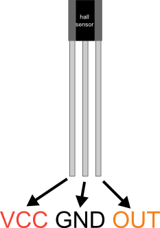


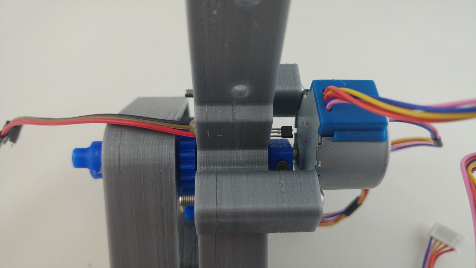


Hi. A question please about this project. All other tutorials I find for the Hall effect sensor A3114 use a 10k pull-up resistor between the data and VCC pins. Is this required in your circuit? Thanks
I didn’t use it but it may improve detection. If other tutorials use it, you can try.
Sorry for the late answer.
Hi, Oscar from Chile, what if I’m using 200 steps/turn steppers?
Hi Oscar!
You’ll have to modify the Arduino code. In my case the motor has some gear reduction and I’m using 8-step sequence, so I need 4096 steps per revolution.
If you have a 200 steps per revolution motor, you’ll need to adapt the code and change a couple of things. You have to look at my code and change all calculations I do with 4096 to fit your motor.
Hope that helps!
Best
makit
Pingback: Buzzer! – makit